In our last post we reviewed the correct techniques for the linear measurement of the LV in the parasternal long axis view. This week we will discuss the aorta and review the morphology and the correct aortic measurement techniques to perform during an echocardiogram.
As a consultant I review thousands of echo images a year. I must admit, it’s a lot easier to sit quietly in a dark office and review images with access to educational resources than it is to wrestle a confused combative patient while trying to perform perfect measurements! So the stories and images of incorrect measurements that I share come with no judgement just an opportunity to learn!
1. Why we measure the aorta in 2D not M-Mode
2. The correct timing and location to measure each segment of the aorta
3. The importance of segmental imaging planes
4. Which artifacts occur with calcification of the annulus
5. How to correctly measure the LVOT in the presence of AS
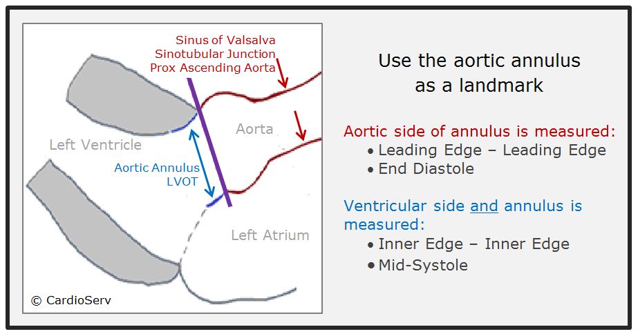
Let’s quickly review some basic anatomy. The aortic root is a geometrically complex structure that includes the aortic annulus, sinus of Valsalva and the sinotubular junction. The aortic root extends from the basal attachments of the aortic valve leaflets within the LV outflow tract to the distal attachment at the tubular portion of the aorta. We will review the latest ASE guidelines and the correct techniques for measuring:
What is the best echocardiographic imaging modality to visualize and assess the aorta?
TEE (transesophageal echo) is better for imaging the aorta when compared with transthoracic echo because of the aorta’s location to the near field of the TEE transducer. The review of 3D echo is beyond the scope of this article and will be addressed in future blogs.
The ASE 2015 guideline recommends measuring the aorta in 2D not M-mode because cardiac motion often results in changes in the position of the M-mode cursor relative to the maximum diameter of the sinuses of Valsalva. I had never really thought about this before but now every time I see an M-mode cursor placed over the aortic root I can help but notice how the heart swings in and out of the cursor plane. ASE reports that this translational motion results in systematic underestimation of the aortic diameter by approximately 2 mm when measuring in M-mode in comparison to 2D measurements.
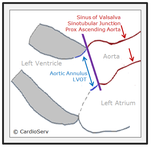
When and where to correctly measure the aortic root and LVOT is important. A trick I use to remember the timing and location is to use the aortic annulus as a landmark. Everything on the aortic side of the annulus is measured end-diastole and leading edge to leading edge (L-L) while the aortic annulus and LVOT are measured in mid-systole and inner to inner edge.
So, why is the aortic root measured leading edge to leading edge (L-L)? This is one of the most common measuring errors I see, as it feels counterintuitive to measure the leading edge of the aorta. Measuring the leading edge can increase the aortic measurement by 2-4 mm. Here is a little history as to why we still measure L-L.
Back in the early days of ultrasound, the aortic root was measured in M-Mode and the L-L technique was incorporated because the interface of the leading edge was easier to delineate. Reference ranges were then established based on this method. However, as the technology of ultrasound advanced and 2D imaging improved it became possible to accurately measure the aorta without needing the bright interface of the leading edge to guide caliper placement. So why does echocardiography still use the outdated L-L technique when neither CT nor MRI uses this method to evaluate size?
The writing committee for the new 2015 Echo Chamber Quantification Guidelines was aware of this discrepancy and took the initiative to try and establish a common standard across all modalities which would have required changing echocardiography to measure the aorta inner to inner. This goal was abandoned though, for the main reason of patient safety.
Think about it…the L-L technique provides statistically larger diameters than an inner-to-inner method, by as much as 2–4 mm. Switching to an inner-to-inner method would produce considerably smaller aortic sizes. Many current guidelines used by surgeons and other physicians, regarding the threshold for recommending intervention, are based on the longstanding reference values of the aorta obtained from the L-L method.
Essentially, switching to an inner-to-inner method would cause some patients to fall below the threshold for intervention, exposing patients who were at potential risk for developing life-threatening complications such as aortic dissection and/or rupture. For this reason the ASE writing committee continues to recommend the L-L method for measuring the aortic root and the aorta.
You will hear mentioned many times throughout this blog series an emphasis on evaluating each structure on its own independent plane regardless of the surrounding structures. The same holds true for the aorta. The aortic root and proximal ascending aorta often lay on a plane that is more medial than the long axis left ventricle. To optimize the aorta independently of the LV you may need to move the transducer towards the sternum and/or up an intercostal space or two. The goal is to display the maximal diameter of the aorta.
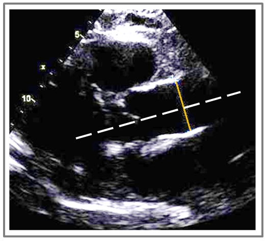
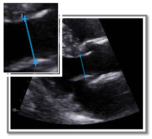
Here is a sample of an echo I reviewed with a measurement of the proximal ascending aorta. Can you help me point out the correct techniques utilized?
A. Correct imaging plane
B. Correct timing of cardiac cycle
C. Correct caliper location
D. Both A and B
The correct answer is D.This image demonstrates the correct imaging plane and correct timing of the cardiac cycle. The image was obtained in a higher intercostal window that opened up the aorta to its maximal diameter with an imaging plane independent to the axis of the LV. The diameter measurement is also perpendicular to the aorta (white line identifies the plane of the aorta). In regards to correct timing of the cardiac cycle, the aortic cusps are closed, suggesting end diastole.
So what was incorrect about this image? The mistake was using the incorrect measurement technique of inner to inner measurement. Remember the trick to learning the correct ASE measurement techniques? Everything on the aortic side of the annulus is measured leading edge to leading edge. (L-L).
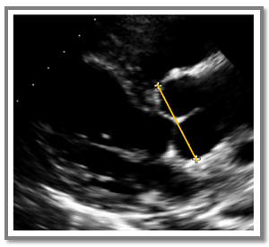
The Sinotubular junction is measured where the curvature of the sinus transitions to the straight walls of the ascending aorta and the Sinus of Valsalva should be measured at the maximum curvature of the right and non-coronary aortic sinuses. Remember the landmark trick…anything on the aortic side of the annulus is measured in end-diastole and L-L. The Sinotubular junction and the Sinus of Valsalva can often be measured in the same view as they usually lay on the same plane. Hopefully you are getting the hang of this! Let’s look at another image. This time, help me point out the incorrect technique utilized.
A. Measured Leading Edge – Leading Edge (L-L)
B. Sinus measured between annulus and max diameter
C. Measured perpendicular to aortic plane
D. Measured in end-diastole
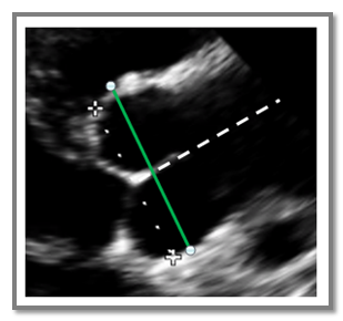
The Answer is B. The Sinus of Valsalva was measured incorrectly because the sinus was not measured at the maximum curvature of the right and non-coronary aortic sinuses. This measurement was taken too close to the aortic annulus and not at the maximum diameter. On this corrected image you can see the green line demonstrates the correct measurement at the maximum curvature of the sinus.
 Correct Techniques
Let’s take a look at the correct techniques that were incorporated for the Sinus of Valsalva measurement.:
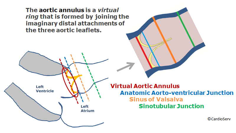
The aortic annulus accounts for the tightest part of the aortic root and although not a true anatomic structure, the aortic annulus is a virtual ring that is formed by the imaginary joining of the distal most uppermost attachments of the three aortic leaflets. The red line in the diagram represents the plane of the virtual ring while the blue represents the actual anatomic junction between the aorta and ventricle. In echocardiography we measure the virtual ring for the aortic annulus measurement.
The importance of an accurate annulus measurement has been brought into the spotlight by the ever increasing TAVI/TAVR procedures but currently there is no established gold standard technique for measuring the aortic annulus before a TAVI/TAVR procedure. The ASE and many other cardiac societies recommend the preferred method of 3D TEE or MDCT (Multi-detector CT). For this reason we will dedicate an entire future blog to the correct 3D technique for measuring the aortic annulus prior to TAVI/TAVR. This article will review the correct 2D assessment of the aortic annulus.
Remember the aortic annulus is our landmark regarding correct timing and measurement techniques! The aortic annulus and LVOT are measured using the Inner-to- Inner technique in mid-systole.
– Zoom mode
– Inner edge to inner edge
– Mid-systole (when the annulus is slightly larger and rounder than in diastole)
– Measure at insertion point of right and non-coronary
Aortic annular measurements may be difficult in patients with a calcified aortic annulus due to ultrasound artifact. The calcification can cause both acoustic blooming and attenuation. Both forms of artifact can obscure the interface of the correct location to measure the aortic annulus diameter. As a general rule, the bulges and protrusions of calcium should not be considered part of the aortic wall, and therefore should be excluded from the diameter measurement.
Acoustic Blooming
Acoustic blooming is when a structure outshines adjacent weaker signals. This would be the extra bright signals coming directly off of the bright calcification spots.
Attenuation
Attenuation on the other hand, refers to the shadows that occur below a strong reflector, blocking the signals of structures below the bright calcification.
 Which technique is incorrect?
Here is an example of an aortic annulus measurement that I received. All of the following techniques are correct except one.
A. Measured at the cusp insertion points
B. Measured mid-systole
C. Measured Inner – to – Outer Edge
D. Measured perpendicular to the plane of the LVOT
Answer is C. The annulus and LVOT should always be measured Inner edge -to-Inner edge (I-I). This image shows an incorrect measurement of Inner to Outer edge. Although the top cursor is correctly placed on the inner edge the proximal IVS the 2nd cursor was placed on the outer edge of the anterior mitral valve leaflet.
We all know that the LVOT measurement is required to calculate the aortic valve area (AVA) with the continuity equation. Most of us are aware that the LVOT dimension is squared in the continuity equation which means a small error in the measurement of the LVOT has a big impact on the calculated AVA. This is one of the reasons that ASE recommends measuring the LVOT three times. The largest measurement should be used for the continuity equation as it is more common for the area of the LVOT to be underestimated.
Remember the LVOT is measured Inner to Inner and in mid-systole. (Use the landmark trick to guide you!) ASE guidelines require the LVOT diameter to be measured in the parasternal long axis view. I have seen the LVOT diameter measurement performed in the apical views before. The reason why we do not measure in the apical window is actually a boring physics reason! Axial resolution is better than lateral resolution in ultrasound. In a parasternal long axis the LVOT lies in a plane that takes advantage of the axial resolution while the apical window measurement of the LVOT would rely on lateral resolution which would be a limiting factor.
– Inner-to-Inner
– Mid-systole
– Parasternal long axis view
– Optimize image (gains, focus, TGCs) for clear visualization of the blood-tissue interface
– Small rotations open up the LVOT
– Measure on a perpendicular plane to the LVOT
Before I tell you my all-time favorite tip for correct LVOT measurements look at the 2 pictures below: Would the LVOT diameter measurement be made at the same location, proximal to the aortic annulus, for both of these images?
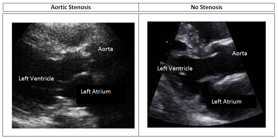
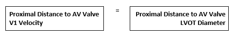
My favorite tip for measuring the LVOT correctly in the presence of aortic stenosis is to pay attention to where you measure the V1 LVOT velocity in the apical window. When obtaining the V1 velocity in the presence of aortic stenosis, if the Doppler cursor is backed away from the aortic valve (5-10mm), to avoid pre-valvular acceleration then the location of your 2D LVOT measurement in parasternal long must also be backed away from the aortic valve the same distance.
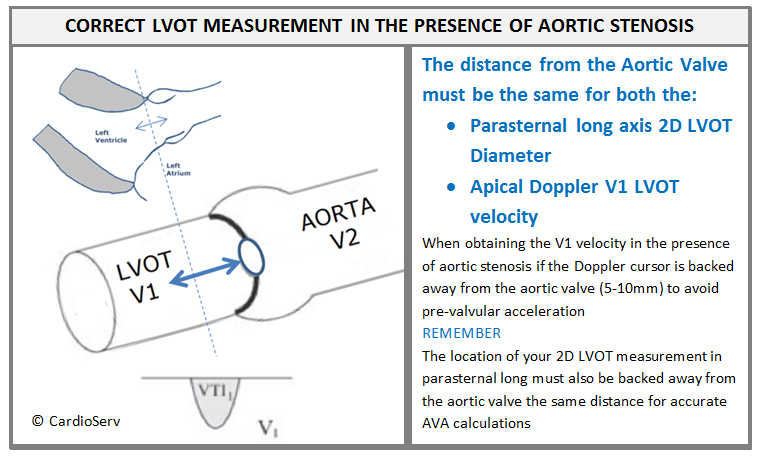
Example: If your V1 velocity is obtained with the Doppler cursor gate 10mm proximal to the aortic valve be sure your parasternal long axis 2D measurement of the LVOT is measured 10mm proximal to the aortic valve
In the absence of pre-valvular acceleration the American Society of Echocardiography states that it is acceptable to measure the LVOT at the level of the annulus. So with this information if we look back at the 2 images we just reviewed – one patient had aortic stenosis and some pre-valvular acceleration while the other patient has no aortic stenosis and no pre-valvular acceleration. Would the LVOT diameter measurement be made at the same location, proximal to the aortic annulus, for both of these images?
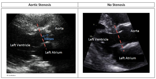
The correct answer was no. The correct location to measure the LVOT diameter in the patient with aortic stenosis (assuming the V1 velocity was measured 10mm proximal to the aortic valve to avoid pre-valvular acceleration) is 10mm proximal to the aortic valve.
I hope that with each blog you walk away with one or two pieces of information that you can implement into your daily scanning practice. This week we covered a lot of information on the correct way to measure the aorta, including the proximal aorta, aortic root and LVOT. Through case study presentations we reviewed some common mistakes to avoid.
Here at CardioServ, as accreditation consultants, we provide valuable, clinical support and training as part of our accreditation consulting services. The Echo Accreditation process includes the submission of aortic stenosis case studies to the Intersocietal Accreditation Commission. These case studies are peer reviewed by physicians and sonographers to assess the quality of echocardiograms performed at your facility. Correct LVOT measurement is essential for the accurate assessment of aortic stenosis so remember these techniques when preparing your accreditation aortic stenosis case studies!
1. Measure the aorta in 2D not M-Mode
2. Timing and location
3. Imaging Plane
4. Avoid artifacts when measuring the annulus
5. Perform correct LVOT measurement in the presence of AS.
Sign up for our newsletter and follow us on Facebook to get the most up to date news on cardiovascular imaging!


Aug
2016
May
2019
Jun
2019
Sep
2016
Sep
2016
Sep
2016
Sep
2016
Sep
2016
Sep
2016
Sep
2016
Sep
2016
Nov
2016
Nov
2016
Dec
2016
Jan
2017
Jan
2017
Jan
2017
Feb
2017
Feb
2017
Feb
2017
Apr
2017
May
2017
Dec
2017
Jun
2018
Aug
2018
Aug
2018
Oct
2019
Aug
2020