Last Updated on January 30, 2024 by Hannes van der Merwe
Do you consider yourself naturally curious? If so, this article is definitely for you! If not… this blog topic will spark your interest! This week our guest writer Yvonne Prince is going to show you different ways to perform accurate echo measurements by applying geometric concepts to improve your echo skills.
Coming from a radiologic technology background, correct image acquisition is all about body planes and tons of imaginary lines connecting anatomic structures. I tend to notice the geometry of everyday things such as highways, buildings and vehicles. To the relationship between intersections, sloping roof lines and the shapes of vehicles. I have always looked at ultrasound image acquisition in the same light. I want to demonstrate how geometric structures play a role in our everyday use of ultrasound in regards to measurements and image acquisition.
PRECISION VS. ACCURACY
Do you know the difference between precision and accuracy? Is there a difference? Yes, no, maybe? Is one preferred over the other? While precision can be a good thing, it can also be bad. Let me explain why…
- Precision means the same values are obtained over and over.
- Accuracy is how close a measured value is to the true value.
Here’s a relatable example: You are the kicker for the football team and you always hit the left goal post instead of scoring the field goal or extra point. Wow – you are very precise, but sadly, not accurate at all.
Do you see the difference? Precision is especially important when it comes to reproducibility of a measurement. The examples below show the differences very clearly.
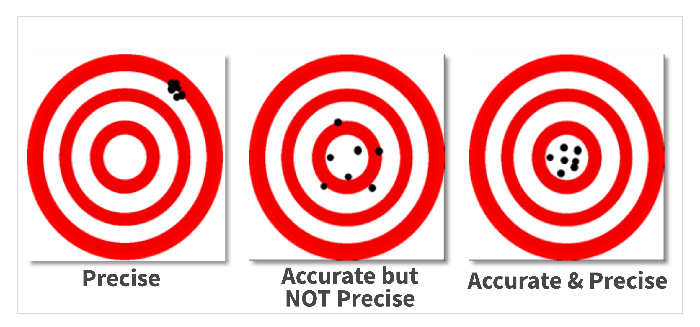
I am sure you have seen this in your career too…
- The last 3 sonographers measured your patient’s IVS at 1.3 cm – indicating hypertrophy was present.
- Today you measure the IVS at 1.0 cm.
So, who is accurate? (Recall the definition- how close a measured value is to the true value)
Often structures within the RV are included in this measurement which causes over-measuring. If you train your eye to better recognize different structures within the cardiac chambers, you can avoid “giving” your patient a diagnosis of LVH.
The old reliable M-mode is a great tool to help train your eye to recognize the details of the cardiac structures. So in this case:
- The 3 previous sonographers were very precise measuring IVS at 1.3 cm
- You are the one who is accurate measuring the IVS at 1.0 cm
IT’S ALL ABOUT THE ANGLES!
Let’s go back to ultrasound physics class for a moment and discuss angle of incidence. In the mug shots below, the subject Alphonse Bertillon is shown from the front and from the side, similar to the way we image.
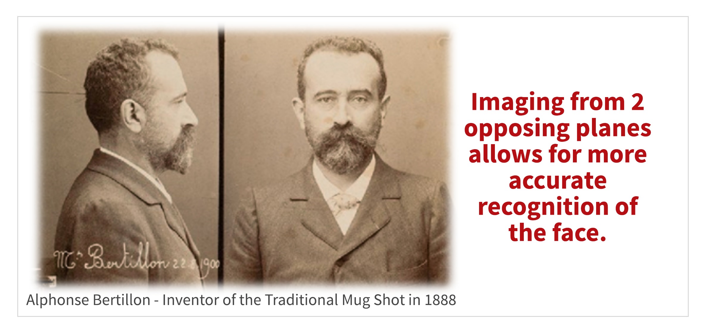
Why 2 views? Seeing or imaging from 2 opposing planes allows for more accurate recognition of face or the structures inside the body we are imaging. Standardizing our scanning in this manner paves the way not only for better image quality, but for more accurate measurements.
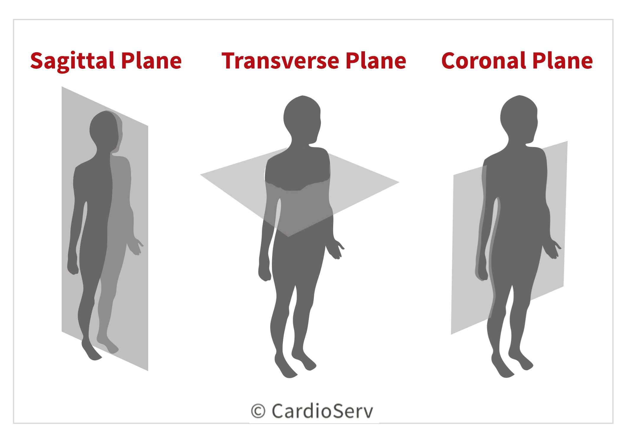
ACCURATE ECHO IMAGING PLANES
In echo, we scan in 3 orthogonal planes:
- Parasternal long axis
- Parasternal short axis
- Apical 4 chamber
Each plane is 90 degrees or perpendicular to the other. This technique allows acquisition of the images required by protocol.
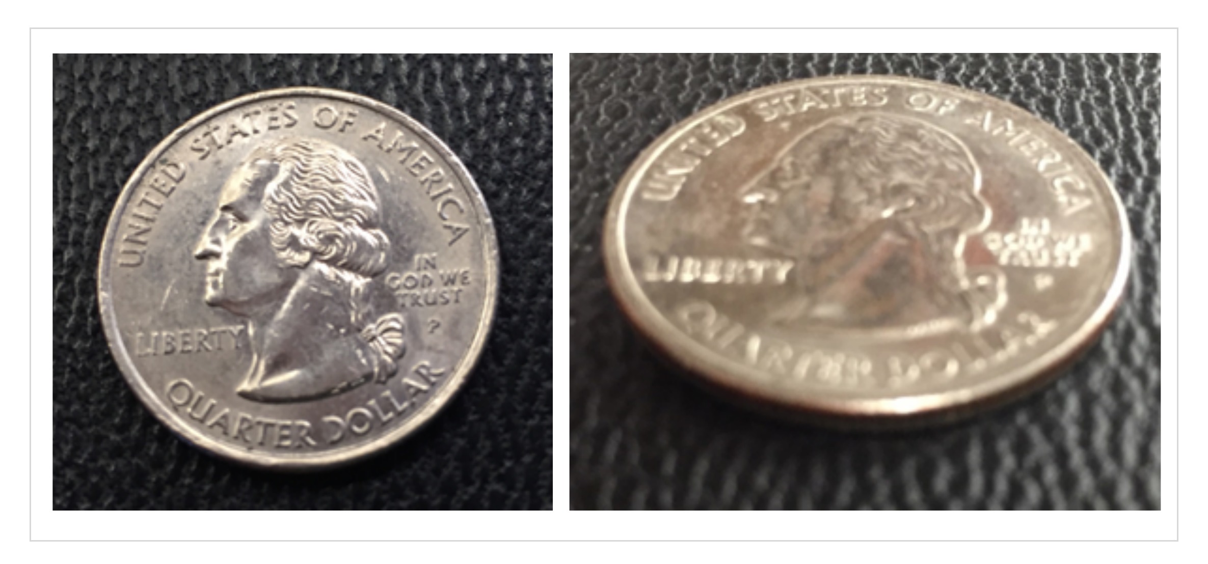
Artist and photographers commonly use the foreshortening technique in their work. Often times the acquisition of ultrasound images can be foreshortened.
In these 2 images of a quarter, notice how the one on the right is foreshortened- appearing oval, rather than round. The facial features on the coin are also blurred on the foreshortened image. This illustrates how critical the perpendicular angle of incidence is in making accurate echo measurements.
The apical and parasternal long axis images below are examples of foreshortening. Notice the appearance of the LV, particularly the apex. When a foreshortened image is used for measurements, (such as Simpson’s biplane) accuracy goes out the window. Remember that Simpson’s biplane is based on geometric “assumptions” as they apply to the cylindrical shape of the LV.
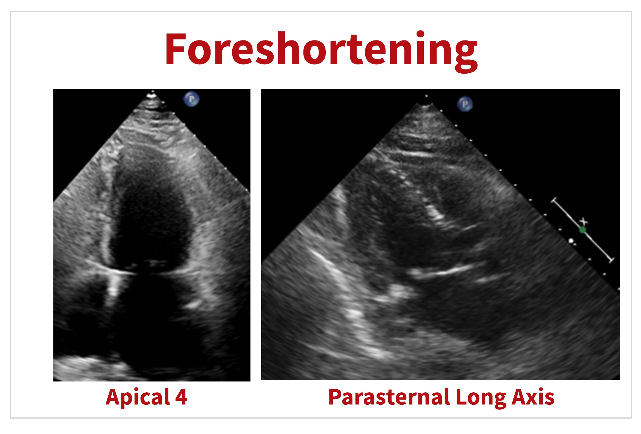
Similar to the way foreshortening is used in art and in photography- foreshortening can be useful in certain cases in ultrasound too. Scanning off-axis can provide a better visualization of certain cardiac structures or pathologies, for example LV apical thrombus.
ACCURATE ECHO MEASUREMENT CALIPER
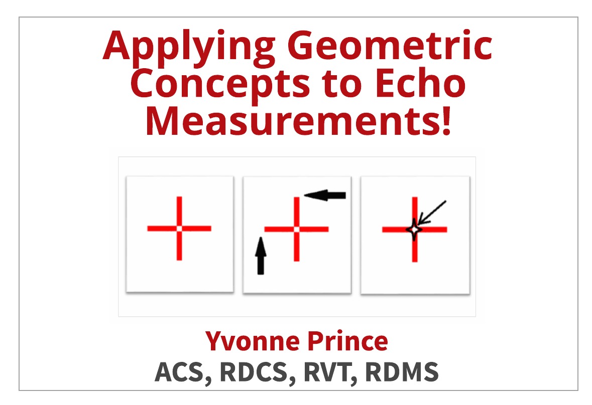
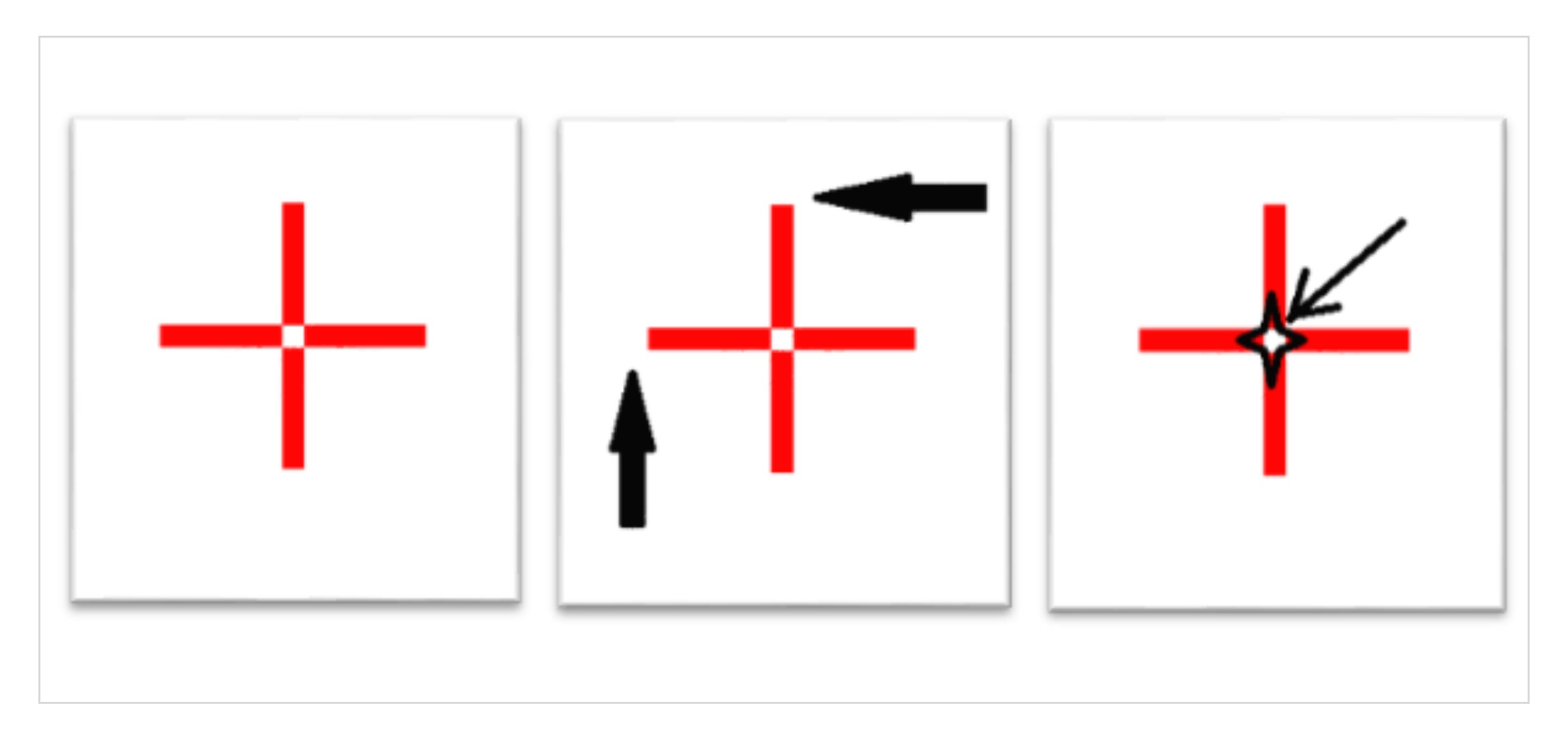
Ultrasound uses crosshairs (or caliper) when measuring structures. How do we know if we are aligning them properly?
Below left is an example of a simple crosshair, which closely resembles the electronic calipers on our ultrasound systems.
- The arrows in the middle image indicate how the calipers are frequently aligned. For example, a peak systolic velocity.
- The image on the right shows the correct way to align the crosshairs.
Remember, we want to hit the target’s bullseye every time- ensuring both accuracy and precision of the measurements.
DOPPLER MEASUREMENTS
Let’s look at some common Doppler measurements in which we can apply geometric concepts.
First answer this question: Can you determine the accurate amount of time it takes for water to boil when placed on high heat by….
- Measuring it with a calendar
- Measuring it with a watch that has a second hand
Of course the answer is B! Likewise, when measuring Doppler or accurate and precise measurements we need to use the best measurement of time by adjusting the sweep speed.
ADJUSTING SWEEP SPEED FOR ACCURATE ECHO MEASUREMENTS
Sweep speed plays a crucial role in the accuracy of measurements in regards to time. The faster sweep speed provides more accuracy in measurements.
- Slow sweep speed is comparable to using a calendar to determine the time it takes to boil water
- Faster sweep speed is comparable to using a watch or clock with a second hand (…more detailed !)
Doppler measurements involving time calculation will be more accurate if more time is provided by increasing the sweep speed.
SWEEP SPEED
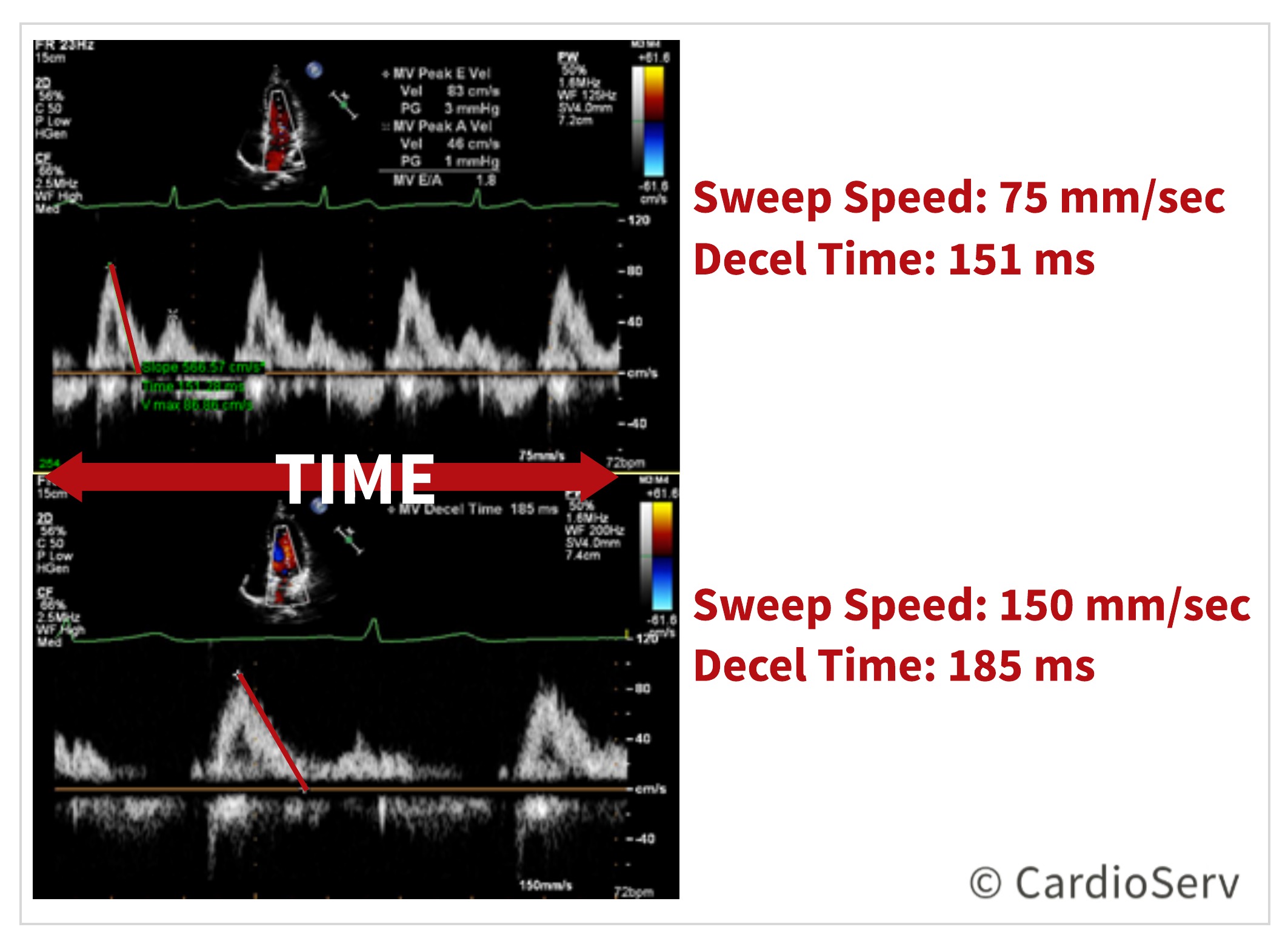
The above image displays the same patient with different sweep speeds and measurements obtained.
- TOP: Sweep speed 75 mm/sec measuring deceleration time 151 ms
- BOTTOM: Sweep speed 150 mm/sec measuring deceleration time 185 ms
The image on the bottom, with the faster sweep speed, allows enough time to evaluate and measure the slope. Acceleration and deceleration time, pressure half-time and VTIs all incorporate time into the equation. We can increase the accuracy by giving ourselves more time by increasing the sweep speed.
HEART RATE
Accuracy of time – for example: heart rate
- Faster the heart rate = faster the sweep speed
ACCELERATION AND DECELERATION TIMES
Positive Slope (uphill)- think of pulmonary artery acceleration time! This measurement is the time it takes for the flow in the pulmonary artery to reach its peak velocity.
- A shortened acceleration time (<120 ms) indicates higher resistance to flow
- It is an indirect marker for pulmonary hypertension
- Increased sweep speed is recommended to improve accuracy
Negative Slope (downhill)- think of mitral valve deceleration time and pressure half-time. Both of these measurements can be used to calculate the mitral valve area. They both involve measuring the deceleration slope. It is often necessary to extrapolate the slope all the way to the baseline.
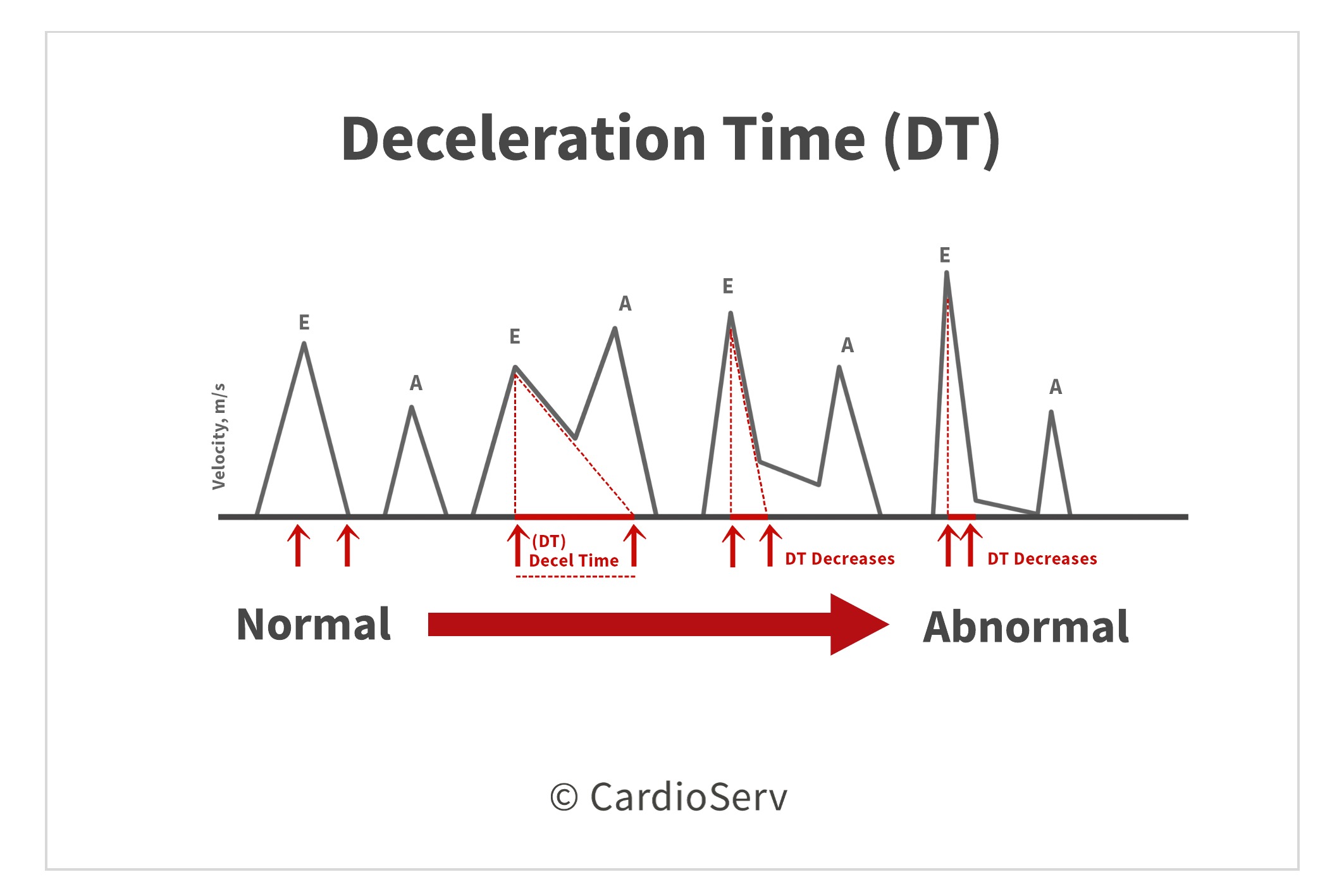
Accuracy of measured slope – for example: deceleration time
- Faster sweep speed = more time to evaluate slope measurement = more accuracy
- Increasing the sweep speed is recommended to improve accuracy.
SUMMARY
Remember that we hold the key to providing optimal diagnostic images for our patients and our readers! If the measurements obtained do not correlate to what is being displayed on the image, we need to take a minute to evaluate this. Could the geometry have an effect on the results? If so, what tools are available to make corrections? Could it be due to the angle of incidence?
3 TIPS FOR IMPROVING ACCURATE ECHO MEASUREMENTS
- Try a different window to better align the beam with the long or short axis of the structure.
- Try off-axis views to better demonstrate pathology.
- Adjust the sweep speed on Doppler measurements.
By taking a different look at routine things, we can often gain insight into how we can improve our skills and ultimately patient outcomes.
We would like to thank our guest writer Yvonne Prince, ACS, RDCS, RVT, RDMS. Check out the Educator Spotlight from last week that introduces Yvonne to our Imaging Community and read her last blog:
Two Ways to Properly Assess TR Jet for Accurate RVSP Calculation

Yvonne Prince ACS, RDCS, RVT, RDMS, FASE
Connect on LinkedIn!